Design and Operation of Voltmeters
Current flows when voltage is present. Without voltage, there is no current. And to be able to measure electrical voltages, you need voltmeters - also known colloquially as voltmeters . Everything you need to know about the rudimentary structure, basic operation and possible applications of voltmeters is now available for you to read.
Voltage meter basics: structure, function & co.
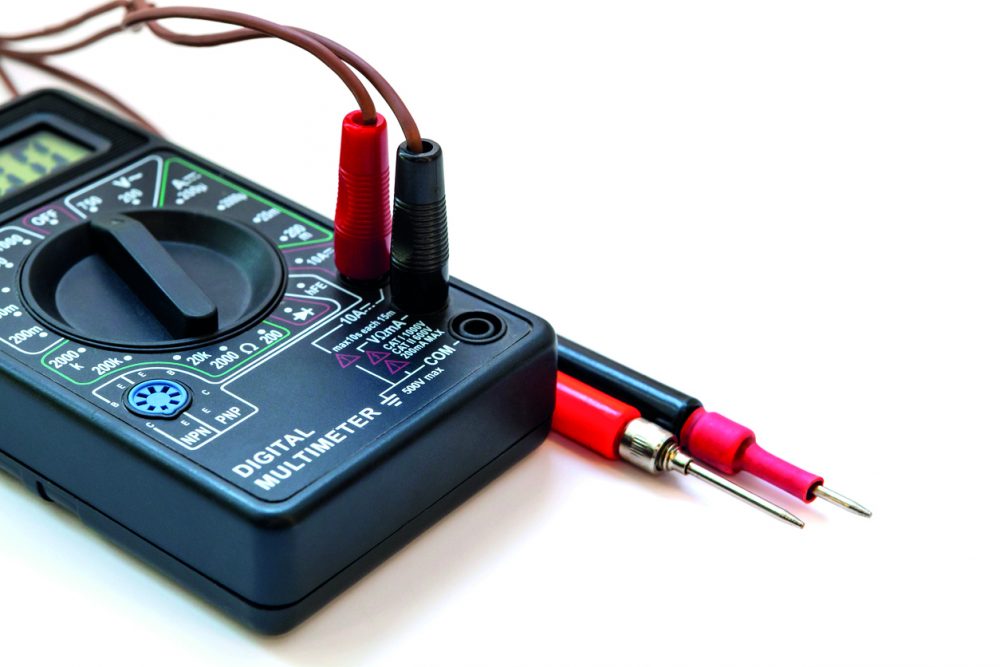
In its basic form, a voltmeter consists of a measuring mechanism (measuring electronics), a display (analog or digital display) and a series resistor or voltage divider.
The structure of a voltmeter is basically quite simple:
- In the upper area there is the display for showing the measured value,
- In the middle is the rotary switch for setting the measurement type and range, and
- In the lower part there are the sockets for inserting the test probes
Why do we need voltage measurement
In order to get an accurate value of electric voltage, voltage measurement must be done. Apart from the traditional use of a voltmeter, more and more users are turning to a multimeter, which can be used to determine several measurement sequences or quantities (current or voltage).
The higher the internal resistance of a voltmeter, the smaller the potential measurement errors when determining the voltage at the consumer.
The voltmeter or multimeter is used to measure the voltage at an electrical device or machine (consumer). The measuring device is always connected in parallel to the consumer – Why is that? The potential (for example, five volts) before (above) and after (below) the consumers must always be collected to obtain the potential difference. This is the actual voltage within the circuit. In addition, it is important that hardly any current flows through the voltmeter, so voltmeters have an enormously high internal resistance.
Also important: For electrical devices of protection classes I and II, a (high) voltage test AC (AC = alternating voltage) is used, for example, to check whether the insulation of the components meets the specified dielectric strength. The functionality of the current-carrying conductors and the safety distance to the housing are determined.
Voltage in a circuit
Voltage sources always have two poles with different charges: a negative pole with an excess of electrons and a positive pole with a deficiency of electrons. In the theoretical representation, electrons move via a conductor from one pole to the other. The greater the difference between minus and plus, the higher the voltage.
Above the consumer is the so-called source voltage. Due to the consumers connected in the circuit, the voltage drops with each integrated electronic device – down to “ground” (0 volts). Kirchhoff’s rule 1: “The sum of all voltages in a mesh is equal to 0.” A mesh describes a closed circuit (circulation of current from one pole of the energy source, to the other) in a circuit.
How is a voltage measurement performed?
Each measurement is preceded by a preparation phase, in which the instrument is set up. Only then follows the execution phase (= measurement process). Before starting the measurement, it is necessary to insert the test probes into the respective sockets. Then select the appropriate measurement value. On the dial, set the value which is the next higher value to the expected measurement result.
It should be noted that the voltmeter is always connected in parallel with the load. This means that the measuring device does not have to be integrated directly into the circuit. The instantaneous voltage value is measured at the voltage source and the voltage drop at this electrical component is measured at the consumer.
5 steps for voltage measurement:
- Set the type of voltage present in the circuit (DC voltage or AC voltage) on the meter.
- Definition of the measuring range for the voltage, this is stored in the device.
- Parallel connection of the voltage meter in the circuit. Tip: If DC voltage is present, make sure that the negative pole of the electrical source is connected to the negative pole of the meter. The same applies to the two positive poles of the source and the measuring apparatus.
- To reduce measuring errors, the measuring range should be switched to the lower third of the scale.
- When reading the voltage: make sure that the set measuring range outputs the maximum value of the scale.
Electrical voltage is determined by the formula
U = W/Q.
W (charge flowing through the closed circuit during a certain period of time) describes the work done to move the charge, while Q indicates the electric charge.
Based on Ohm’s law, the voltage is calculated using the formula
U = I*R.
I is the electric current and R the electric resistance.
Check mains voltages
In the course of renovation work, lamps or sockets are often dismantled. In order not to get a dangerous electric shock, it is recommended to check the mains voltage with a voltmeter. This determines whether there is voltage on the lines and connections.
Caution: Have measurements in circuits >33 V/AC and >70 V/DC performed only by qualified personnel!
Voltage power supplies and multimeters from Bürklin Elektronik
Bürklin Elektronik, as a leading distributor of electronic components, offers an extensive range of high-quality, effective voltage measuring instruments and multimeters, as well as accessory components such as test probes or hour meters. The product features are geared to the respective area of application.
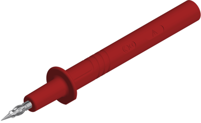
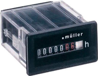
Are the measuring points located under an insulating or oxide layer? Then the use of a test probe with dual function for piercing the protective material is recommended. Or do you want to determine how many hours an electrical consumer has been in operation? Tip: Integrate an operating hours counter into the circuit!


