IO-Link for more Safety in Automation
For more economic and functional safety in the operation of modern machines and systems, the integration of intelligent devices is required. IO-Link systems offer a solution by integrating them into existing circuits, systems, production facilities and other constellations. We explain what an IO-Link system is, how it is structured and what advantages it brings to the application.
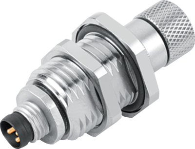
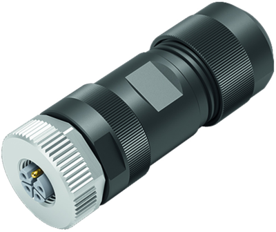
IO-Link applications make machines more effective, safer, more flexible, and more economical. Standardized M8 industrial connectors and M12 industrial connectors allow systems and devices to be put into operation quickly. In addition, manual programming of sensors and actuators is no longer necessary. The parameter data for the components originates from the controller, which means that the system is ready for operation more quickly. Early detection and transmission of data from the system makes maintenance work and service more efficient. Damage can be identified in time and, if necessary, new maintenance concepts can be designed.
What is IO-Link?
IO-Link is an automated communication system. Integrated into this system are sensors and actuators for translating electrical signals into mechanical movements. The IO-Link system is based on a standardized communication or automation system, in the IEC61131-9 standard.
The internationally valid IEC61131-9 standard defines the fundamentals of programmable logic controllers (PLCs). These are devices for controlling and regulating machines and production facilities. A PLC, unlike a hardwired connection-programmed controller, is programmed digitally rather than analog.
What is the structure of an IO-Link system?
In its simplest form, an Input-Output-Link network (IO system) consists of an IO-Link master and one or more IO-Link devices. Thus – as mentioned above – sensors or actuators. In addition, an IO-Link system has one or more IO-Link ports connected to a HUB.
- Sensors: are comparable to the sensory organs of a human being. They are the eyes, ears and touch organs of the respective component or an electrical device. Sensors are essential components of electronic systems and are used to detect physical or chemical quantities. After the information has been recorded, sensors convert the data into electrical signals. All types of connectors are suitable for use on the sensor side – it is recommended that the minimum cross-section be observed. Rule of thumb: For a cable length of 20 meters, a cross-section of at least 0.34 millimetres must be maintained. Unshielded cables can be used.
- Actuators: are also described as drive technology units. The task of an actuator is to convert a received electrical signal into a mechanical movement. Another function: to implement the change in physical variables (for example, pressure or temperature). Actuators thus actively intervene in the controlled process.
- HUB: refers to a node where several components of a system converge. HUBs are integrated in Ethernet networks, for example. The use of a HUB increases the failure safety of a system: if a cabling is defective, not the entire system is affected, but only the damaged part of the network.
Actuators and sensors form a unit in an IO-Link. Changes are recorded via a sensor, for example. The corresponding signal is forwarded to the actuator, and it performs the programmed function.
How does an IO-Link system work?
In an input-output link system, communication signals from electronic systems are processed and controlled. The link master receives the signals from the sensors and the mechanical movements of the actuator. It processes the information received and then transmits further commands to the system. The process data is transmitted cyclically. The communication within the circuit is (often) based on the 3-wire circuit.
3-wire circuit – an extra round for a clean measurement result
To minimize measurement errors, a third conductor is connected to the measuring resistor and the measuring device. Because: In classic 2-wire circuits, distortions often occur because the lead resistance is included in the measurement result.
This is a problem especially with devices or circuits that are exposed to larger temperature fluctuations (for example in industrial plants). To reduce system failures or measurement errors, a “bypass” is integrated in the system. The adjusted measurement result is determined via this.
5 advantages of an IO-Link system
- circuits over long distances are made possible – IO links are therefore often integrated in industrial plants.
- standardized procedures increase compatibility with other systems; sensors and actuators are available quickly and in large numbers. This reduces costs and installation times if components need to be replaced.
- intelligent IO masters are not only used to transmit commands, they can also evaluate data, in other words, communicated information (for example, in the case of early or graded signal messages).
- short response times: Damage or malfunctions are detected quickly, and the system can counteract accordingly in time to prevent further damage.
- easy integration (retrofitting) into existing systems: IO-Link are usually integrated below a network as a backup system.
IO-Link system for intelligent plant concepts: safety for next-generation industrial plants
IO-Link systems are an important factor in safeguarding and optimizing production processes in industrial plants. The IO-Link system is preferably used in the environment of production automation to connect sensors and actuators to the system. IO-Link enables sensors and actuators to communicate, devices can be parameterized centrally, and diagnostic information can be transmitted from the device to the controller.
The individual IO-Link system components for IO-Link installation are available in the online store at Bürklin Elektronik – smart technology for powerful systems.

